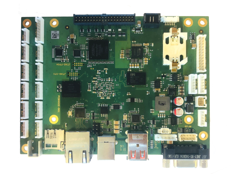
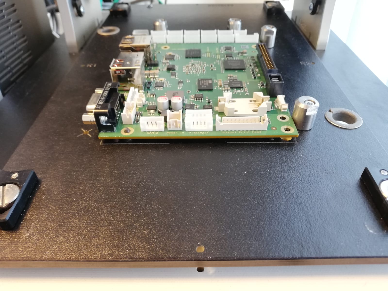
In fact that this CPU board has standard interfaces like ethernet and RS232, we connected the device under test (DUT) directly to a normal computer.
The host computer writes the initial U-Boot into the RAM of the DUT and it becomes alive. After that the DUT boots from a USB stick ware a customized yocto OS including all test software is stored on.
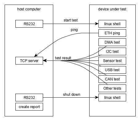
The test itself is running on the device under test. The host and the DUT are communicating via TCP/IP and serial interfaces. The host monitors every single test and logs the whole console output from the DUT. All test results and the console output will be stored in a PDF file generated with python.
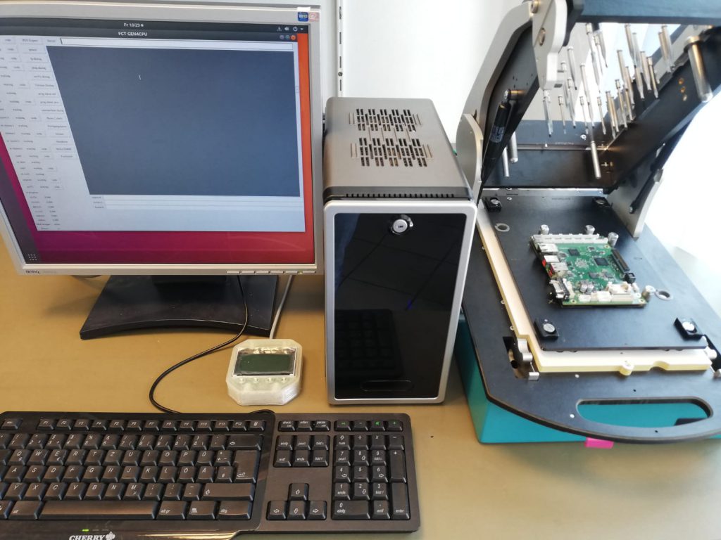
The host is running a ubuntu operating system so we were able to rapid prototype a simple test application, which is written in python. This includes a crude grafical user interface and automatic test reports in PDF, JSON and other file formats.