What we Do
We develop and manufacture electronic system components for industrial applications since 1985. Our primary focuses are modern embedded computer systems which are based on ARM and X86 architectures.
Electronic engineering
- computer on moduls, QSeven, eNuc boards, baseboards
- Complete systems
- Boxed-PC
- Advanced system electronics, visualization and control, electronics for field buses
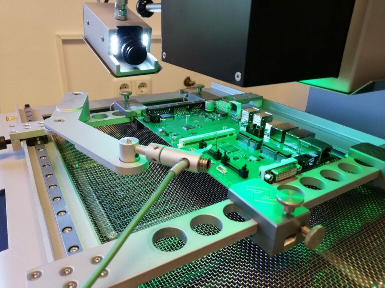
- Function test systems
First launch of newly developed designs
In collaboration with our partners we are doing SMT assemblies for prototypes. Before the device gets powered up the first time, we check all solder connections by an initial optical inspection. Sometimes you can see simple faults like shorts on IC pins without digging any deeper.
Afterwards when everything seems ok we are powering the board up step by step. These steps could be flashing a firmware to a PMIC or microcotroller, measurung quiescent current, voltages and other significant units. In case the board is working properly until that point we are going to check the functions of the assembly by writing and executing crude test programs.
cadence® is a software solution mainly consisting of schematic and pcb layout program. It is one of the most widely used solution for the creation of circuit boards.
It provides us a powerful design constraint manager to avoid failures. This means we can rout faster and benefit from advanced routing technology. Big manufacturers like AMD®, Intel® etc. work with cadence® products, in that case approved layouts with high integrity and complexity can be reused. A perfect layout is essential for a good performance and increases lifecycles.
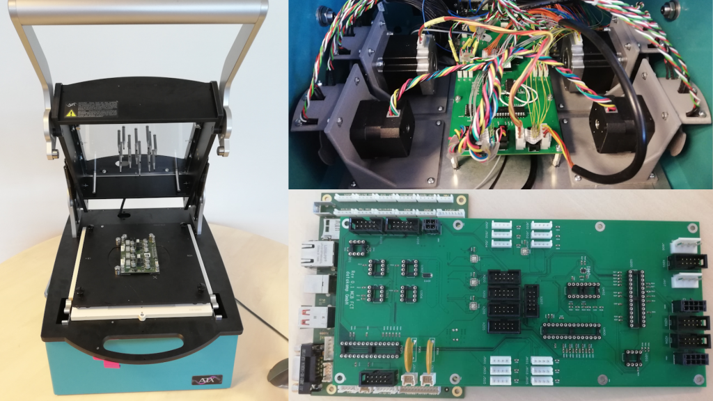
Test solutions for complete systems
The steadily shrinking structures of microelectronics also increase the complexity of an PCB assembly. In this connection, the effort of testing raises considerably. To keep the quality up, it is necessary to guarantee, that all boards are testet in equal conditions.
To meet that requirement, we are developing semi automatic testers for embedded devices. This includes the development of electronic hardware and software. The mechanic components like the housing, needle beds and wire wrap connections are second source. Small customized parts can be manufactured in our house with different kinds of additive manufactuing. Standard interfaces that need to be tested are: I2C, SPI, Ethernet, CAN, USB, GPIO and others.
When switching to semi-automatic testers, you benefit from time savings and consistent quality. In one case we were able to shorten the time for testing from two hours to two minutes.
Software development
- Board Support Packages (BSP)
- X86 BIOS development
- UEFI
- Yocto Linux
- Chromium Browser
- Coreboot
- Programming languages: C, C++, C#, Qt, Python, JavaScript, HTML
Browser based application with Chromium™ open-source web browser
This is an application that runs within the Chromium™ Web browser. The instructions, typically written in a combination of HTML5 and JavaScript, are embedded within the Web page that is downloaded from a Web site. Typically the Web site is provided from a Webserver running on the embedded device itself. The advantage of browser-based applications is that they can run in a Windows PC, Mac or Linux machine, since all Web browsers are required to
render HTML5 and execute JavaScript in the same manner, no matter their environment. We extensible support the Chromium™ open-source web browser project from Google. This is a fast Web browser which supports all modern Web standards. We have the know how to fully customize the Chromium™ browser in the YOCTO™ Linux environment to meet exact the requirements of the embedded browser based application.
U-Boot – Universal Boot Loader
U-Boot is a bootstrap software that runs on different processors, we are using it especially for ARM microcontrollers. It is mainly used in the field of embedded systems. Flexible configuration options during compilation make it possible to generate special variants for different applications. Even at runtime, the behavior can be influenced by extensive command line commands or a shell (Hush from BusyBox project) as well as persistently storable environment variables.
The development of the project is based on Linux. Parts of the source code come from there. Special emphasis was placed on booting Linux images. The software can be compiled via cross-compiler on an x86 PC for the target platforms. Support for this is offered by toolchains such as crosstool, the Yocto™ Project or OpenEmbedded.
Yocto™ Project – create a custom Linux-based system
Coreboot – Open Source project for BIOS firmware in most computers
Coreboot is an Open Source project to replace the proprietary BIOS firmware found in most computers. Coreboot has the task to initialize the hardware components in an embedded system and then executes the boot process, called a payload. The payload can
be a specialized application that run directly from firmware, run operating systems from FLASH drives or implement firmware standards, like PC BIOS and UEFI services. An example of a PC BIOS is the payload SEABIOS.
We use Coreboot only for x86 computer architectures.
System development
- Construction of castings, frames, cassettes, component part carriers and foil veneers
- Creation of system- and manufacture documentations
- Develop and maintain a well-documented SDLC (System Development Life Cycle) for all system and application development processes
Hardware Development with Dassault Systèmes SOLIDWORKS®
DLP Printing – Digital Light Processing
DLP 3D printing technologies make use of a (liquid) photopolymer resin that is able to cure (solidify) under a light source. These printers are equipped with a projector screen which flashes an image of a layer all at once.The precision is limited by the resolution of the projector. Each pixel takes place in a surface of 50×50µm.
With this kind of technique we are manufacturing customized parts in a quick and precise way. Especially when parts need to be more temperature stable, this can be the solution. Parts are temperature stable up to over 200°C.
To the right you can see a little mounting plate for 65mil needles. It was made to test a computer on module with outer dimensions of 30x30mm.
FDM Printing – Fused Deposition Modeling
FDM Printers use a process called Material Extrusion. A spool of filament provides the material supply. The filament is fed into a heated nozzle where it melts. Along specific coordinates, which are defined in a sliced 3D object file, the head of the 3D printer moves over the building plate, creating the solid.
FDM printers and the corresponding feeding materials are pretty cheap. For parts with low technical requirements this technique is a very good solution to quickly manufacture prototypes.
Here you can see customized motor mountings for a function tester. Light barriers are roughly sensing the movements of the motor.
Production
- Serial production
- Initial software launch
- Pre and final assembly
- Final test of assembly, equipment and system
- Specific climate test procedures
- CE certifications in collaboration with our partners
- Vakuum packing
- Picking, packaging and shipping
- Computer / Circuit Board Repair and Rework Services
Climate Chamber – Advanced Condition Testing
We are using the Weiss WT 180 climate chamber to perform burn in tests. This testing process will force certain failures to occur under monitored conditions. In this way we research the resilience of our products.
All newly developed products have to pass our 24 hour stress test. Every 15 minutes the devices restarts, while a specific temperature curve between 0 to +65°C is followed. If a device fails to start it will be sorted out.
In general we are able to program temperature curves in a range of -40 to 180°C. So we offer our customers the service to perform burn in test für every single delivered device to fit their needs.
Reworkstation & Repair
Sometimes PCBs are faulty even after the AOI (Automated Optical Inspection) and ICT (in Circuit Test), but they fail in the FCT (Function Test). With our rework station we are able to exchange faulty ICs. It gives us the ability to precise place, solder and inspect ICs with highly integrated structures like BGAs.
The Ersa Hybrid Rework HR 550 delivers a homogenic warming of the whole assembly by applying energy from a downside up infrared heating element. It provides a 1500 W hybrid heating element to desolder and solder SMT components up to dimensions of 70 x 70 mm. To rework a target hardware the station manages customizable temperature profiles. The component that has to be reworked is applyed with a high precision vacuum device.
Embedded Computers or modules are more complex today than ever before, but despite how severely damaged they may be, they can be repaired. Indeed the high value of many embedded Computers or modules demands that they be repaired. Even less expensive assemblies maybe require repair because just-in-time manufacturing and tightly controlled production runs leave little room for shortage. Just a few years ago, such Systems were much simpler and repairs were relatively easy. Today’s they have fine pitch components, ball grid arrays and fine line circuits making them a challenge to repair. Yet, we’re driven by simple economics and must repair damaged assembly whenever possible. Whether repairing damaged internal circuitry or reworking cold solder joints. the technicalknowledge and manual skills needed for high reliability repair and rework are indeeddemanding.