Function Test

Motor Driver Board


Entirely of aluminium

The device under test

  • 2 Stepper Motors
  • 2 BLDC Motors
  • Encoder Sensor Inputs
  • CAN Interface
  • 2x SPI Interface
  • 24V Supply
  • 15V inernally generated
  • 3V3 internally generated
Function Test PCB - Customized test hardware
  • Acts like a gateway between host computer and device under test
  • Power switches for power supply
  • Analog switches for signal lanes
  • I2C interface
  • GPIO port expanders to control switches
  • Analog digital converter to monitor voltages
  • Polyfuses in case of fault

Rapid prototyping

  • Manufactured with filament 3D printer
  • Mounting for the Motor
  • Mounting for light barriers
  • Encoder disc to measure the movements of the motor
No deal without software​
C program for embedded linux​

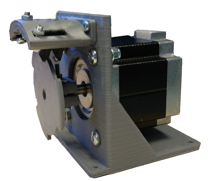
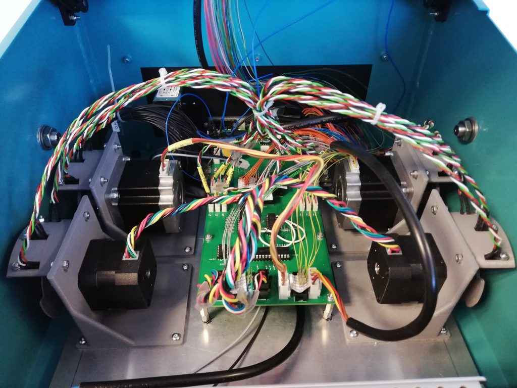
The motor driver board is an additional board to an ARM-CPU board. So we used that board to test it. We try to meet the test conditions as close as possible with the clients application. For the motor driver board we used the original motors of the end use.

On the ARM-CPU board runs a customized Yokto Linux witch means we needed to develop software with the corresponding SDK. The test software is developed in C programming language to have direct access to the hardware.

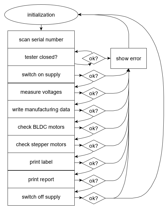
On the right side you can see a simplefied schematic how the software works in general.

First all data structures will be initialized to make sure  that no data from the last device under test is used. After that the software is wating for closing the test adapter. And here comes the automation. All interfaces will be checked in a state machine –  one after another. At the end a label will be printed in case the test was successful.

Some Pictures of the assembled FCT​

Here you can see the wiring between all those components. Sometimes the test adapters need to change the location. For that the components are screwed tightly to a mounting plate.

You are interested in or have any questions? Please feel free to